Volume : 1 | Issue : 2
Research
Geometrically-mediated snap-off of water-in-oil emulsion droplets in microfluidic flow focusing devices
Jia Yao,1 John Oakey2
1Department of Petroleum Engineering, University of Wyoming, USA
2Department of Chemical Engineering, University of Wyoming, USA
Received: February 26, 2018 | Published: March 26, 2018
Abstract
Microfluidic channel networks allow the control of flowing fluids within structures with length scales on the order of single or tens of micrometers (µm). This affords the opportunity to mix and separate fluids with fine precision and, in the case of immiscible multiphase flows, generate stable emulsions with well-controlled sizes and size distributions. It is generally well understood that emulsion droplet size can be regulated by carefully balancing capillary-associated parameters, such as relative fluid velocity, with the interfacial tension of the immiscible phases. Channel size and geometry, particularly that of the junction where fluids merge in microfluidic flow focusing (or “pinch flow”) devices, has been shown to scale droplet size and bound the lower droplet size. Channel constrictions or “nozzles” are commonly employed to amplify the extensional flow at channel junctions, but their function has not been quantified and is, therefore, not well understood. This paper describes the use of geometry as a tunable parameter in microfluidic droplet generator design by focusing upon the effect of nozzle geometry (relative width, length and depth) upon droplet snap off behavior. Our results show that nozzle geometry can dramatically influence droplet size by shifting its snap-off position, an effect that can be anticipated by Raleigh-Plateau theory.
Introduction
Microfluidic multiphase flow has been the subject of significant attention over the past decade. The previous investigations on multiphase flow process are mainly focused on macro-scale level,1–3 and some significant results have been got with the help of capillary tubes.4,5Washburn provided an analysis on the displacement of air by mercury by using a capillary tube, which demonstrates the basic force competition for flow in co-current.6 A model of capillary tube with a sinusoidal varying diameter was developed by Olbricht and Leal, unlike the straight tube, an extensional flow was introduced in this flow process.7 The glass capillary tube of triangular cross-section model was built by Mason and Morrow to get several basic features of the capillary behavior of highly complex porous materials in the multiphase flow process.8 With the rapid development of microfluidic technology, microscale emulsions have emerged as a powerful and high-throughput platform within a variety of scientific and industrial disciplines. Microfluidic droplet and encapsulation technologies have been applied to molecular assays,9,10 cell biology,11–13 cryopreservation,14–16 and particle synthesis17–20 in innovative ways with technologically significant results. Microfluidic droplet generation provides exquisite control over droplet size with high monodispersity, which is because of the force competition during micro droplet formation in the channel constriction of “nozzle”. Therefore, it is necessary to get the fundamental understanding of the effect of nozzle geometry on the micro-droplet formation.
Snap-off is a kind of phenomenon that the wetting(continuous) phase pinches the non-wetting(dispersed) phase into droplets, because of the unstable interface between multiphase,21 during oil displacement process. In essence, snap-off is a kind of emulsion droplet. Typically, emulsion droplets are formed due to the force competition between the multiphase. As inertia can be neglected in microfluidic flows, the balance of viscous force and interfacial tension force controls emulsion droplet formation process,22 leading to capillary number known as the parameter that determines the size of emulsion droplets. However, in multiphase flow process, the associated velocity field are complex,22which should be influence by the geometry of channel. To realize the potential influence of geometry of channel, flow focusing microfluidic devices with different constriction geometries are used in our experiments.
In this paper, we report a methodology for simulating snap-off droplets formation in the microfluidic devices with the various nozzle geometries. Snap-off is accomplished with droplets formed in various volumes at a co-flowing junction. We present an analytical model to understand this kind of change trend. Besides, and our results also proved that the snap-off formation position was also influenced by the changing geometries.
Materials and methods
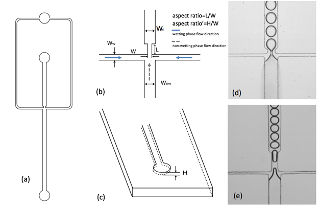
To simulate co-current imbibition flow, wetting phase mineral oil and non-wetting phase deionized water were pumped through the inlets, as shown in Figure 1(a). Flow rates for both wetting and non-wetting phase could be controlled at 2µL/min, namely flow rate ratio (wetting versus non-wetting) is 1 by syringe pump, in order to avoid the influence of flow rate on snap-off droplet size.
Figures 1(d)-(e) show the stable snap-off droplets formations in the devices with different geometrical constrictions. Obvious difference in snap-off droplets sizes was observed due to different constriction geometries. For snap-off droplet, the extension was defined as the ratio of droplet length to its circumference πWd, where Wdwas the width of channel where droplet flowed in. According to the classical Rayleigh-Plateau instability, in which a cylindrical liquid thread can reduce its total surface area by breaking when its length exceeds its circumference. In another word, the spherical droplets are always in the most stable condition. Droplets in Figure 1(d) were the typical spherical, stable ones, and the volumes of them could be calculated by using V=4/3πR3. However, for droplets in Figure1(e), they had cylindrical shapes, and this type of shapes formed due to the limitation of the downstream channel geometry. And these droplets still existed stably, mainly because of the surfactant, while the study of surfactant dynamics was beyond of the scope of this work. For these droplets, the volumes of them could be calculated by using V=A*d, and A was the surface area from two dimensions, which were measure by ImageJ, an open source image processing program designed for scientific multidimensional images.
Microfluidic devices were fabricated with polydimethylsiloxane(PDMS), a transparent elastomer, using soft lithography techniques. The PDMS device was bonded to another glass slide, and then, treated by Aquapel to get the homogenous hydrophobic wettability on the micro channel surface. In our experiments, non-wetting phase water snaps off in a wetting phase of mineral oil. A surfactant, sorbitan monooleate (Span 80), at 1.0 wt % was added to the mineral oil to stabilize the snap-off droplets against coalescence. This reduces the interfacial tension between deionized water and the surfactant-mineral oil solution to γ=21.13mN/m, as measured using a pendent drop equipment. Syringe pumps were used to control the infusion of fluids. In each device, snap-off droplets with different volumes were generated at the constrictions with various geometries.
To tailor the influence of geometry on snap-off droplet size, we simulated a co-current imbibition flow in the microfluidic device, as shown schematically in Figure 1. Typical geometrical dimensions are shown in Figure 1(b) and (c). For this asymmetric device, the channel width for wetting phase was Ww=30µm, the channel width for non-wetting phase was Wnw=160µm, and after these two kinds liquids met, they flowed into the downstream channel, whose width was Wd=160µm. The vital geometry part of the device was the constriction, whose width W and length L were designed for different values. Besides these two dimensions, microfludic devices with different depths, H, as shown in Figure 1(c), were also applied in the experiment. Therefore, three dimensions changes were conducted in the geometry of constriction to see the influence on snap-off. We defined two parameters: (1) aspect ratio=length/width, and (2) aspect ratio’=depth/width to describe the relationship between snap-off droplet and constriction geometry.
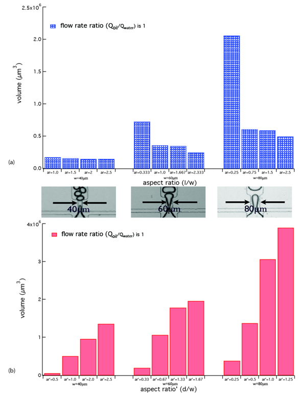
Several devices with different geometries were used to get the influence of constriction geometry on snap-off. The width values of constriction W were set at 40µm, 60µm and 80µm as three groups, and the length values L and depth values D were changed to get different aspect ratios and aspect ratios'. Then, using various devices, we determined the snap-off droplet volumes for different geometries, and plotted the results in Figure 2. In Figure 2(a), the depth value was fixed at 50µm for these three different width groups (W=40µm, 60µm and 80µm). The similar decreasing change trends of droplet volumes were observed in these three groups, with increasing aspect ratios. However, the same aspect ratio did not lead to the same droplet volume in devices with different constriction widths. For example, aspect ratio=1 in microfluidic device with W=40µm and aspect ratio=1 in W=60µm, there was obvious volume difference between them. In Figure 2(b), the length value for different width groups was kept as a constant 60µm, and the depth values were increasing from 40µm, 60µm and to 80µm, leading to increasing aspect ratios'. Instead of decreasing, the droplet volumes increased with the increasing aspect ratios'.
Results and discussion
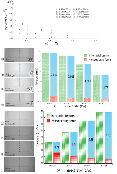
In order to fully exploit the changing trend of snap-off droplet volume, we must elucidate the physics of how these snap-off droplets form, and determine the condition under which it happens. In essence, the formation of snap-off is that the velocity field in the wetting phase deforms the emerging interface of non-wetting phase, drawing it through the constriction. During this process, inertia can typically be neglected according to the characteristic of microfluidic flows, so that the balance of viscous drag force and interfacial tension force controls the snap-off droplet formation. Thus, capillary number, , was regarded as the appropriate dimensionless parameter for describing these processes. Then, 8 devices with different geometries were used to show the relationship between droplet volume and capillary number, in Figure 3(a). The droplet volume decreased with the increasing capillary number, which means droplet was easier to form. As capillary number reflects the relative effect of viscous force versus interfacial tension, the increasing capillary number could be caused by increasing viscous force or decreasing interfacial tension. Combining these, for snap-off droplet formation, viscous force works as the motive force, while interfacial tension serves as the resistant force. The snap-off droplet cannot form until the force balance between these two forces are reached.
During snap-off formation process, the force competition between viscous drag force and interfacial tension force determines the droplet size. At the constriction part, the flow of non-wetting phase can form a "neck", due of the functions of these two forces. This "neck" will become narrower, finally be pinched off when the force balance reaches. At certain position, the fixed distance from the onset of constriction, there is a diameter di, representing the diameter of the "neck" can be measured by ImageJ. Then, the modified Stokers formula can be used to calculate viscous drag force, and μ is viscosity of wetting phase, d is diameter of droplet, diis diameter of neck, v is flow velocity of wetting phase, and vdis the stream-wise velocity component of expanding drop, and can be calculated by using . And using , interfacial tension force can be got. Thus, for the same width value group, take W=80µm as an example, different snap-off droplet for different aspect ratios are shown in Figure 3(b)-(e), and the relationship between these two forces and aspect ratio is shown in Figure 3(f). Both interfacial tension force and viscous drag force are decreasing with the increasing aspect ratio. And the force difference between these two forces also decreases at the same time. While, still for this width value group, the increasing aspect ratio' leads to different changing trend for these two forces, as shown in Figure 3(k). Instead of decreasing, the force difference is increasing with the increasing aspect ratio'. Obviously, the smaller force difference is favor for reaching the force balance, then, the increasing aspect ratio leads to a smaller force difference, which makes force balance can be reached early before droplet grows bigger, however, the increasing aspect ratio' leads to bigger force difference, which takes longer time to reach force balance. That is why the increasing aspect ratio determines smaller droplets, while increasing aspect ratio' results to bigger snap-off droplets.
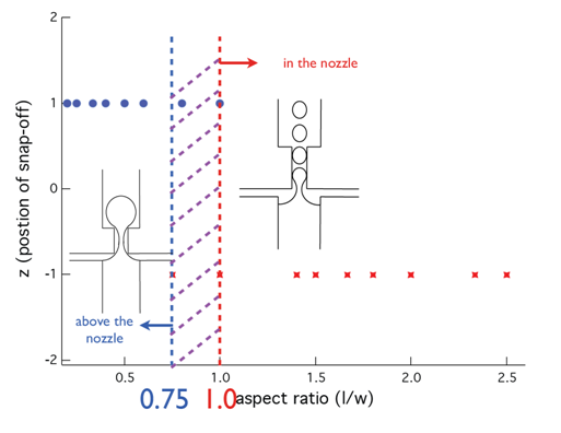
Besides the snap-off droplet volume, the position of snap-off formation is also influenced by the geometry of constriction. For 18 devices, coming from different width values groups and with different aspect ratios, two kinds of snap-off formation positions were observed during the experiment. One position was above the nozzle and the other was in the nozzle. Figure 4 shows the relationship between aspect ratio and snap-off formation position, and these two kinds positions occurred in the certain aspect ratio scope. When aspect ratio is smaller than 0.75, snap-off occurs above nozzle definitely, while aspect ratio is over 1.0, formation position of snap-off is in the nozzle, and when aspect ratio in the range between 0.75 and 1.0, there is a transition zone, where snap-off may happen above the nozzle or in the nozzle.
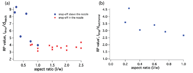
Essentially, Rayleigh-Plateau theory could describe the formation of snap-off, since it is a kind of droplet. The relationship between aspect ratio and Rayleigh-Plateau value is shown in Figure 5(a). For snap-off forming in the nozzle, their Rayleigh-Plateau values are bigger and close to π,in the range of 3.55 to 4.97. The formation of snap-off in the nozzle can be regarded to follow Rayleigh-Plateau theory. However, Rayleigh-Plateau values for snap-off forming above the nozzle with varying nozzle widths are much bigger than π. Rescaling their Rayleigh-Plateau values by using the droplet length and the hydraulic diameter of outlet channel, regardless of the influence of nozzle, we can get the new Rayleigh-Plateau values for them, as shown in Figure 5(b). The new values are in the range of 2.988 to 4.083, considering the measure errors, these Rayleigh-Plateau values follow the theory. Therefore, the nozzle with smaller aspect ratio has little influence on the snap-off formation.
Conclusion
Using the concept of geometrically mediated microfluidic devices, we have demonstrated the significant influence of constriction geometry on snap-off, including snap-off droplet size and snap-off formation position. Snap-off droplet size decreases with increasing aspect ratioand increases with increasing aspect ratio’, and snap-off droplet formation follows Rayleigh-Plateau instability. As our fabrication is using soft lithography methods, it allows precise manipulation of results and close to the real phenomena in the reservoir
Acknowledgements
This work was supported by University of Wyoming School of Energy Resources and Wyoming INBRE.
Conflict of interest
The authors wish to declare no conflict of interest for the manuscript “Geometrically-Mediated Snap-off of Water-in-Oil Emulsion Droplets in Microfluidic Flow Focusing Devices.”
References
- Kam SI, Rossen WR. A model for foam generation in homogeneous media. SPE J. 2003;8(04):417–425.
- Kovscek AR, Radke CJ. Pressure-driven capillary snap-off of gas bubbles at low wetting-liquid content. Colloids Surf Physicochem Eng Asp. 2003;212(2):99-108.
- Khatib ZI, Hirasaki GJ, Falls AH. Effects of capillary pressure on coalescence and phase mobilities in foams flowing through porous media. SPE Reserv Eng. 1988;3(03):919–926.
- Andrew M, Bijeljic B, Blunt MJ. Pore-by-pore capillary pressure measurements using X-ray microtomography at reservoir conditions: Curvature, snap-off, and remobilization of residual CO2. Water Resour Res. 2014;50(11):8760–8774.
- Unsal E, Mason G, Morrow NR, et al. Bubble snap-off and capillary-back pressure during counter-current spontaneous imbibition into model pores. Langmuir. 2009;25(6):3387–3395.
- Washburn EW. The dynamics of capillary flow. Phys Rev. 1921;17(3):273.
- Olbricht WL, Leal LG. The creeping motion of immiscible drops through a converging/diverging tube. J Fluid Mech. 1983;134:329–355.
- Mason G, Morrow NR. Capillary behavior of a perfectly wetting liquid in irregular triangular tubes. J Colloid Interface Sci. 1991;141(1):262–274.
- Wang CJ, Li X, Lin B, et al. A microfluidics-based turning assay reveals complex growth cone responses to integrated gradients of substrate-bound ECM molecules and diffusible guidance cues. Lab Chip. 2008;8(2):227–237.
- Dittrich PS, Manz A. Single-molecule fluorescence detection in microfluidic channels—the Holy Grail in μTAS? Anal Bioanal Chem. 2005;382(8):1771–1782.
- Hazel J, Krutkramelis K, Mooney P, et al. Changes in cytoplasmic volume are sufficient to drive spindle scaling. Science. 2013;342(6160):853–856.
- Lai S, Wang S, Luo J, et al. Design of a compact disk-like microfluidic platform for enzyme-linked immunosorbent assay. Anal Chem. 2004;76(7):1832–1837.
- Hung PJ, Lee PJ, Sabounchi P, et al. Continuous perfusion microfluidic cell culture array for high-throughput cell-based assays. Biotechnol Bioeng. 2005;89(1):1–8.
- Fleming KK, Hubel A. Cryopreservation of hematopoietic stem cells: emerging science, technology and issues. Transfus Med Hemotherapy. 2007;34(4):268–275.
- Song YS, Moon S, Hulli L, et al. Microfluidics for cryopreservation. Lab Chip. 2009;9(13):1874–1881.
- Heo YS, Lee H-J, Hassell BA, et al. Controlled loading of cryoprotectants (CPAs) to oocyte with linear and complex CPA profiles on a microfluidic platform. Lab Chip. 2011;11(20):3530–3537.
- Nie Z, Li W, Seo M, et al. Janus and ternary particles generated by microfluidic synthesis: design, synthesis, and self-assembly. J Am Chem Soc. 2006;128(29):9408–9412.
- Nisisako T, Torii T, Takahashi T, et al. Synthesis of monodisperse bicolored janus particles with electrical anisotropy using a microfluidic Co-Flow system. Adv Mater. 2006;18(9):1152–1156.
- Xu S, Nie Z, Seo M, et al. Generation of monodisperse particles by using microfluidics: control over size, shape, and composition. Angew Chem. 2005;117(5):734–738.
- Gangwal S, Cayre OJ, Bazant MZ, et al. Induced-charge electrophoresis of metallodielectric particles. Phys Rev Lett. 2008;100(5):058302.
- Roof JG. Snap-off of oil droplets in water-wet pores. Soc Pet Eng J. 1970;10(01):85–90.
- Lee W, Walker LM, Anna SL. Role of geometry and fluid properties in droplet and thread formation processes in planar flow focusing. Phys Fluids. 2009;21(3):032103.
