Volume : 1 | Issue : 3
Review
A literature review of asphaltene entity, precipitation, and deposition: introducing recent models of deposition in the well column
Mahdi Zeinali Hasanvand, Mostafa Montazeri, Marzieh Salehzadeh, Mojtaba Amiri, Mohamad Fathinasab
Research Institute of Petroleum Industry, Tehran, Iran
Received: July 09, 2018 | Published: September 20, 2018
Abstract
Organic precipitations are highly sticky and hard if some asphaltenes are present. This causes a deposition problem to occur when thermodynamic conditions are suitable for sedimentation in a wide range of production processes. This range may start from the porous media around the oil well and continue to the production pipes. Asphaltene exists in many light and heavy oil reservoirs, which often causes problems in the process of crude oil production. Asphaltenes have up to hundreds of carbon molecules in its structure which will be precipitated as a result of natural pressure drop, temperature changes and oil composition changes.
In natural depletion, the main cause of asphaltene precipitation is the reduction of pressure. Due to the process of oil production from the well, which is accompanied by simultaneous reduction of pressure and temperature, this molecule is deposited to the tube wall during three stages of precipitation, growth and deposition, and causes flow obstruction.
The precipitated asphaltene generated in the process of oil production from the reservoir closes the well and transmission lines. In the process of exploitation, the chock valves, separators, and other equipment in the way are blocked and broken. In refineries and petrochemicals, the presence of even small amounts of asphaltene results in a significant drop in the efficiency of catalysts and other additives. Therefore, before the reactions are performed, attempts are made to remove as much of these materials as possible from oil.
In this paper, scientific literature related to the chemical structure and thermodynamic behavior of the asphaltene molecule has been investigated in order to provide clear overviews of the asphaltene precipitation and deposition, and the processes that lead to its occurrence in the well. Then, the precipitation and deposition of asphaltene in the well column and its effective factors are investigated.
Keywords: Asphaltene entity, precipitation, deposition, well column, modeling
Asphaltene and its molecular structure
Asphaltenes are complex compounds with a high number of atoms. The thermodynamic behavior of these compounds, due to their chemical nature, changes from one reservoir to another and often does not have a specific molecular weight. Asphaltene dissolves well in aromatic solvents such as toluene, benzene and xylene due to having aromatic structures itself. However, it does not dissolve in normal alkane solvents such as normal hexane or normal heptane. For this reason, to remove asphaltenic material from the crude oil, the normal alkane is added to it. The concentration of asphaltene in oil generally depends on the heavy oil content. By increasing the density of oil, the concentration of these materials increases in the crude oil composition. The primary structure of the asphaltene molecule consists of aromatic rings. The number of these rings can vary from three to more than ten rings per molecule. Asphaltenes are mainly hydrogen and carbon, with one to three atoms of nitrogen, oxygen, or sulfur per molecule. For this reason, they are also referred to as NSO compounds. Non-hydrocarbon atoms are likely to be part of a hydrocarbon ring or attached to a ring. The weight percentage of asphaltene compounds in scientific sources is as follows: 80 to 86 percent by weight of carbon, 6 to 8 percent hydrogen, 2 to 9 percent sulfur, 0.5 to 2 percent oxygen, 0.5 to 2 percent nitrogen and 0.1 to 0.2 percent of the metal (often nickel, vanadium and Iron).1
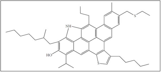
From the structural point of view and chemistry decomposition, there are two different theories of the structure of the asphaltene molecule. The first structure is known as the ocean or island model, according to which a monomer of asphaltene has a molecular mass of 500 to 1000 Daltona (equivalent to about 500 to 1000 g / mol of molar mass). This monomer consists of six to eight aromatic rings, which surround them with the aliphatic branches of the heterogeneous atom. This structure is shown in Figure 1.
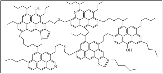
Another model proposed for the asphaltene structure in scientific resources is the archipelago or rosary-type, assuming that asphaltene monomer is composed of cluster poly-condensing groups of five to seven aromatic groups. These clusters are interconnected through their aliphatic branches and sometimes by polar bridges. The structure proposed in the archipelago model is shown in Figure 2.2
|
Figure 2 Asphaltene monomer structure based on archipelago model2 |
Extensive research has been carried out in recent years to determine the actual structure of the asphaltene molecule and its molecular properties, such as molecular mass and size. Among them, in 2007, Herod et al.3 claimed that the asphaltene molecule consists of two islands of monomer that is formed by a part of a mass of one mega Dalton and one section weighing about 5 kDa. In this research, considering the high number (one mega Dalton) for molecular mass, it is likely that a floc of asphaltene has been used. Strauss et al.4 found in 2008 that, contrary to the previous conclusions, asphaltene does not have an island structure, and the structure should be similar to the archipelago model. The most complete and recent conclusion in this field is related to Mullins and his colleagues based on the results of measuring molecular mass based on 4 methods of molecular diffusion and 7 mass spectrometry methods. Based on the results of this work, it was found that asphaltenes are a single monomer structure with a molecular weight of about 750 to 1,000 Daltons, and this molecular weight corresponds to an ocean or island structure.5
Regardless of the structure of asphaltene molecules, asphaltenes in crude oil should be defined as a cut. The difference between asphaltene cut and the other oil cut called ‘Saturated, Aromatics and Resins’ is solubility and polarity. Based on this cutting, saturated materials are non-polar materials with no ring structure and contain only carbon and hydrogen. Aromatic materials, like saturated materials, are made only of carbon and hydrogen, but in their molecular structure, there are one or more aromatic rings. In this case, resins of semi polar material have circular structures and a few non-polar elements such as nitrogen, oxygen and sulfur. However, they have the ability to dissolve in saturated alkanes such as normal heptane (insoluble in propane and soluble in heptane normal). Based on this division, asphaltene is the only polar cut that is not solved in the middle alkanes, and in addition to the NSO, there is the possibility of metal elements in its structure. The differences between these four major cuts are presented in Table 1 .
Name of oil cut |
Ability to dissolve in alkanes |
Polarity |
Constituent elements |
Carbon number |
Ring structure |
|---|---|---|---|---|---|
Saturated material |
Completely solved |
Non-polar |
Carbon-hydrogen |
> 20 |
Do not have |
Aromatics |
Completely solved |
Non-polar |
Carbon-hydrogen |
20 - 60 |
have |
Resins |
Solved |
Semi-polar |
Carbon-hydrogen, nitrogen, sulfur |
30 - 100 |
Have (benzene) |
Asphaltene |
Will not be resolved |
polar |
Carbon-hydrogen, nitrogen, sulfur, oxygen and metals such as iron, and zinc . |
< 100 |
Have (benzene) |
Table 1 Properties of crude oil-based cuttings based on polarity and dissolution
*Asphaltenes are molecules that do not melt and their thermal cracking are at temperatures above 300-400 °C, so that no melting point can be imagined.
In the resin molecule, there is a polar group on one side and an aliphatic chain on the other. When the asphaltene molecules are connected and agglomerate together, an increase in polar positions on the set provides positions for the bonding of resins. The longitudinal aliphatic ends of the resin cause the asphaltene molecules to be colloidal and ultimately suspend it in the oil.
aDa (equivalent to kg)
Effective processes for blocking the wellbore by deposition of asphaltene
Different processes are effective in creating asphaltene deposition in transmission lines, including oil wells. What is most commonly mentioned in the scientific literature are thermodynamic equilibrium (precipitation), kinetic process (solid particles accumulation and growth), and transfer processes (related to particle deposition). Furthermore, each of these three processes will be investigated and the factors affecting them will be introduced.
Asphaltene precipitation process
Asphaltenes are suspended in the oil under favorable conditions by the resins. In fact, the phenomenon of suspending or solubility of asphaltene particles in crude oil can be described as a thermodynamic equilibrium phenomenon. The change in any factor that interrupts this equilibrium can disrupt the state of the suspension and cause the asphaltene particles to accumulate together and eventually degrade them. Production of oil, especially the methods used in the second and third stages of oil recovery, often causes some changes in flow behavior, phase equilibrium properties, and reservoir properties. These changes can interfere with the thermodynamic equilibrium and cause asphaltene precipitation in the reservoir or column of the well.
In the event of instability of the asphaltene molecule, this molecule is separated from the liquid phase, and thermodynamic balance is suppressed because of the resins and maltenes, which, as a result, releases asphaltene particles stick together. Asphaltenes are surrounded by polar heads of maltenes and resins. In fact, due to the instability caused by the drop in pressure, the asphaltene molecules are separated from the liquid phase and form the micelle. Each micelle has a nucleus of asphaltenes and tails of non-polar sequences of resins, which are referred to as fines. The presence of resins around the asphaltenic core causes suspended asphaltene to precipitate. The same properties of resins are used to manufacture asphaltene industrial inhibitors.5
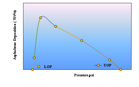
From the thermodynamic point of view, the effective parameters in the formation of asphaltene precipitation include pressure, temperature, composition, or concentration. In an oil that is susceptible to precipitation, that precipitation is initiated at a pressure above the bubble pressure, and the amount of precipitation increases by decreasing the pressure to the bubble point. The maximum amount of precipitation is observed at the point of the bubble. By decreasing the pressure from the bubble point, the amount of precipitation will also be reduced, so that the precipitation formed in the liquid phase will eventually return and disappear. The onset points for the formation of precipitation at the top and bottom of the bubble point are UOPa and LOPb. Figure 3 illustrates the behavior of asphaltene precipitation relative to pressure at reservoir temperature for the actual Shadegan oil field.
The effect of temperature on the variation of precipitation content has been reported in various scientific sources. In some articles, precipitation has increased with increasing temperature, and in some others, different behavior has been observed. Nakhli et al.,6 in 2009, reported that asphaltene precipitation decreases in light oils (API> 30), and in heavy oils (API <20) asphaltene precipitation increases with increasing temperature. In addition, in one of the fields in the south of Iran, the Fahliyan layer, similar findings have been observed in oil. In this oil with a high degree of API 38, the amount of precipitation is decreasing with increasing temperature. At 294, 248, and 190 degrees Fahrenheit, the precipitation content is 0.46, 0.52 and 0.53 percent, respectively.
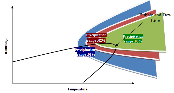
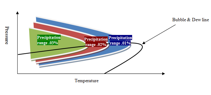
The effect of temperature and pressure on the precipitation in the phase envelop is called “precipitation phase envelop.” Due to the different effect of temperature on phase envelop, the precipitation phase envelop behavior will be in two general conditions. In the first type, which is generally common for heavy oil, there is a range of precipitation yield limited by temperature reduction, which indicates the direct effect of temperature on precipitation (increasing temperature leads to an increase in precipitate). In the second type, which is generally popular in light oil, the temperature range is limited to precipitation, which indicates the reciprocal effect of temperature on precipitate yield. The general idea of these two types of thermodynamic behavior is shown in Figure 4 and Figure 5.
The third most important thermodynamic factor in the formation of asphaltene precipitation is the concentration of crude oil. Generally, the concentration of asphaltene precipitation decreases with increasing gravity (decreasing density). In heavy oil, the concentration of this oil cut is more than 5%, but in lighter oils, the concentration of asphaltenes is sometimes negligible. For example, in the oil of Fahliyan and Sarvak layers with a gravity of 35.5 and 21.9, the asphaltene precipitation content is 0.3 and 7.7% by weight, respectively.
Cutting of asphaltene in crude oil can be susceptible to precipitation due to the percentage of stable groups such as Resins and Aromatics and unstable groups such as saturated materials. In some oil samples, despite the high concentrations of asphaltene in the oil composition, due to the high amount of resin and the shortage of saturated materials, asphaltene precipitation does not form in any pressure. Unlike this, sometimes due to the low concentrations of asphaltene in the oil composition because of a high concentration of saturations, it can be confronted with the acute precipitation of asphaltene (for example, the Fahliyan layer in the Darkhevin Field). In addition to the primary compounds of oil, the composition change due to the addition of precipitant or the mixing of oil with different layers can interfere with the thermodynamic stability of the oil and cause precipitation of asphaltenes. For this purpose, the initial tests named IP143, SARA and De Boer diagrams are defined (based on standard procedure ASTM D6560, D2007).
Asphaltene particle growth process
In static conditions, as a result of instability of the thermodynamic equilibrium conditions, asphaltene is removed from the liquid phase as precipitated nuclei. The size of the formed nuclei increases as time goes on and the instability factor continues. The growth process and the attachment of a part of the nuclei cause a spectrum of particles of different sizes. In this case, the density of some particles (mass) increases so much that it is placed on the threshold of deposition due to the weight of the mass. The mass of a few nuclei of asphaltene is called the floc. With the continuation of instability, a portion of the asphaltene is deposited, the size of which is sufficiently enlarged starts to settle down.7
The size of the first asphaltene nuclei is about 20 Angstroms (equivalent to 2nm),8 which has 8 to 10 molecules of asphaltenes. Rastegari et al.9 studied the reciprocation process of mating, assuming the definition of nuclei as particles of 1 micron and flocs as particles up to 400 microns in the atomic-hepta-atomic system. According to these observations, the operation of turning these nuclei into a floc is a reversible operation, which is why, by adding some resin or dispersing agent to asphaltenes, it could prevent the asphaltene from being deposited.
In 2006, Angel et al. investigated the process of asphaltene particle growth under atmospheric conditions by adding alkane precipitant using optical microscopic images. They showed that the starting point of precipitation is a function of time and concentration of precipitant materials. In most of the previous studies, due to the fact that experiments were performed in less than an hour, the effect of time on asphaltene precipitation was neglected. But Angel showed that the precipitation process is a slow phenomenon that can take several hours (Figure 6). In this experiment, asphaltenes were first diluted with 90% toluene and then heptane was added as a precipitation agent.10
Their study indicated that the time to grow asphaltene in heavy oil is higher than that of light oil. The time required to form asphaltene flocs with a diameter of more than 0.5 μm varies from a few seconds to several months depending on the precipitation concentration.
In kinetic terms, Kevin et al.11 and Tabish Maqbool12 showed that asphaltene precipitation is a function of time. They showed that the solid phase precipitation rate is a function of time, temperature, and concentration. The particle size distribution also has a normal pattern. Therefore, the use of thermodynamic models along with motion models should be considered the kinetic aspect of the asphaltene precipitation process.
It should be noted that in most studies, the particle size is more than 1 micrometer. That is, with the fact that the asphaltene particles are distributed from a molecule. The asphaltene molecule is about an angstrom (0.1 nm), the initial nucleis are about 20 angstroms (2 nm), and the particles are at least 1 micron (1000 nm). Therefore, the kinetic state of asphaltene, rarely has been studied in the range of 1 nm to 1000 nm. This is a scientific gap in the studies of asphaltene deposition, which can be a good topic for scientific research.
Asphaltene deposition process
The asphaltene deposition process on the surface of the tube is naturally divided into several stages. In the first step, with the achievement of thermodynamic equilibrium, fluid temperature and pressure, asphaltene molecules prepare to change phase from liquid to solid. First, asphaltenes are bound together by solid molecules and produce nano-sized nuclei. The primary nuclei are small because of their small presence and the presence of resin molecules around them is suspended in crude oil. From this stage, they are called the stage of formation of precipitation. Over time, as a result of two factors, the nuclei collision and particle growth, the size of the particles of asphaltene is enlarged and micronized. If the particle size is such that the liquid medium does not have the ability to suspend it, the gradient of the temperature and particle concentration can transfer them to the surface, or the metal or mineral surface of the system will be able to adsorb solid particles, then Asphaltene particles begin deposition. In moving environments such as pipelines and wells, a finite time is needed to transfer solid particles of asphaltene from liquid to wall and adsorption to wall. Due to the turbulence of the flow in column, the asphaltene particles in the wall should pass through three environments: turbulent core, buffer layer and a laminar sublayer.11,13
In fact, only a fraction of the precipitated flocs are deposited in the pipeline and stick to the wall of the tube. This percentage is a function of various variables such as particle size, particle distribution, particle density, flow density, flow viscosity, flow velocity, gravity, surface material, flow pressure and temperature. The most challenging and ambiguous parts of the problem are to determine the effect of each of these variables on the percentage of solids deposited in the pipeline. One of the most important goals is identifying these impacts in the field of asphaltene deposition in future research.
a Upper Onset Pressure
b Lower Onset Pressure
Modeling of asphaltene deposition in the well column
The deposition process of asphaltene to the well column is a mass transfer phenomenon and is a function of the particle size of the flocs and time. The solid particles of asphaltenes in crude oil have a magnitude of one nanometer to a few dozen micrometers. The type of forces affecting the penetration of these particles is different in the process of meeting. Different models for estimating the coefficient of deposition in vertical pipelines are presented. The main mechanisms that have been considered in determining the coefficient of deposition include Brownian motion,14,15 eddy motion in turbulent flows,13,16 inertia,17 shear force,18 gravitational force and thermophysical forces.19 So far, two main directions have been presented in the modeling of asphaltene deposition processes in the well column. The first orientation of the deposition process is a mass transfer phenomenon, and it only deals with the calculation of particle mass transfer coefficients and its effect on the characteristics of the system. In the second direction, in addition to considering the issue of mass transfer, the process of producing asphaltene nuclei, their collisions and the asphaltene deposition are considered as dependent kinetic reactions. In the following section, two massive and reactive transmission views will be introduced.
Modeling of asphaltene deposition in a well column with the approach of transmission phenomena
Escobedo and Mansoori20 presented a model for asphaltene deposition in a well column by molecular, eddy and inertia diffusion. This model is applicable to the single-phase and turbulent wells where the variations in density and viscosity are negligible in relation to the length. In this study, they investigated the effect of particle diameter, oil viscosity, and oil production rate verses changing the coefficient of the deposition. During this study, it was found that the coefficient of deposition for particles smaller than 1000 nm is a molecular diffusion function and has a slight variation in the diameter of the particle. However, for particles with diameters greater than 1000 nm, the deposition coefficient is a momentum function and increases with increasing particle diameter.
Mirzayi et al.19 modeled the forces acting on the asphaltenes particles in the flow of oil in a horizontal tube modeling process. They defined the six main forces of Brownian, drag, gravity, thermophysical, buoyancy and shear motion as effective forces in the asphaltene meeting. They investigated the effect of particle size, flow velocity and temperature gradient on deposition, and showed that in the horizontal flow lines the role of gravity and temperature gradients in formation of sediment is more effective than other forces.
Eskin et al.21 developed a model for asphaltene deposition based on the mass transfer of particles in turbulent flow. They considered a population balance model along the pipeline (with respect to time) to distribute the particle size of the asphaltene. Also, they considered Brownian and Eddy diffusions for particles of asphaltene with different size to the wall surface. This model has three adjustable parameters including critical particle size, particle-particle collision, and particle-to-wall collision that are obtained by Couette test, while not referring to the asymmetric precipitation thermodynamics of the solution. In this model, only small particles, less critical, may be deposited. All particles move irregularly (Brownian motion). However, in the vicinity of the wall, the probability of particles for a solution is a function of the particle size and fluid composition. It should be noted that due to experimental limitations, particle size distribution has not been reported and the results of simulation in this field have been fixed. On the other hand, for the purpose of adjusting the results of the model with experimental data, the critical particle size was suggested to be 30 nm, with only the dominant Brownian motion (molecular diffusion) influence in this size. In this case, the critical mass is equal to the particle size in which the forces of van der Waals and Drag equal. For viscosity of 1 to 10 centipoises, a diameter of 15 centimeter and a speed of 1 to 3 meters per second, this size varies from 5 to 30 micrometers.
Schirdel et al.22 compared different models of asphaltene deposition in the tube. They consider Friedlander and Johnstone,14 Beal,13 Cleaver and Yates,23 and Escobedo and Mansoori17 models. During this study, it was determined that these models are capable of modeling the transfer of asphaltene in crude oil. They also concluded that the deposition coefficient decreases with increasing velocity and decreases the wall temperature of the well. Finally, they proposed the models of Beal13 and Escobedo and Mansoori17 for the sake of comprehensiveness and considering the relaxation time for modeling deposition in the well.
Hashmi et al.,24 also with the view of mass transfer, suggested a model for asphaltene deposition in which the entire transfer process occurs in a laminar sublayer. Asphaltene deposition is obtained on a metal surface with a molecular diffusion mechanism. They used asphaltenes for their atomic-heptane systems in atmospheric conditions to validate their model. Deposition of asphaltene was evaluated by injection of a mixture of oil and sediment into a capillary tube. There was a correlation between model prediction and laboratory data. However, this model has only developed for the laminar flow. Further studies are needed to validate this model in the more realistic conditions of fluid flow in a pipe or column well.
Modeling the asphaltene deposition in the well column with the approach to reacting
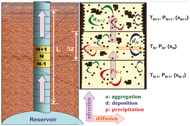
In 2010, Vargas et al.25 provided a framework for simulating the deposition rate in oil wells. They used the PC-SAFT thermodynamic model to estimate the gas-oil-asphaltene equilibrium. In this study, two models of kinetics of asphaltene and asphaltene deposition were added to the thermodynamic model. Based on the proposed framework of Vargas et al., deposition of asphaltene with two kinetic models is divided into two parts: micro-aggregate and aggregate, of which only micro-aggregate particles have the potential to sit on the well wall. In this model, it is assumed that there are only two particles (micro-aggregate and aggregate) of different sizes in the system. On the other hand, deposition of asphaltene is a function of the concentration of micro-aggregate particles. In fact, for the asphaltene to be deposited on the well wall, three processes should be taken into account: precipitation (microaggigates), formation of aggregation, and deposition (microaggregates). In addition, both groups of Microgravity and Aggregate particles can be transmitted in the flow path during the convection process. The process of formation of deposition in the well column is presented in Figure 7 according to the model of Vargas et al.25
|
Figure 7 An Overview of the Asphaltene Sedimentation Stages Based on the Vargas et al. Model25 |
In this study, due to the lack of laboratory and field data, the hypotheses for precipitation coefficient, aggregation coefficient, and coefficient of deposition were determined and showed that increasing the aggregation coefficient decreases asphaltene deposition during the tube.
In later studies of this group, Kurup26,27 used this asphaltene deposition simulator as a predictor in such a way that all of its kinetics parameters (including three precipitation, aggregation and deposition reactions) were determined. In this study, the field data reported by Kabir et al.28 (Related to the Kuwaiti Meratat Area) were used to adapt to the proposed model. Simulation results showed that the model has a good ability to estimate field results; however, some of the model constants have many changes compared to laboratory measurements. In another study, field data related to a horizontal pipeline was used. Over time, the loss of frictional pressure increased, which attributed it to asphaltene deposition. The Darcy-Wiesbach formula was used to calculate the frictional pressure drop. The remarkable thing about this model is that all experiments were carried out on liquid-phase single-phase systems. They also proposed a method for converting deposition coefficient measured in a lab pipe test to a pipeline scale.
Shutte et al.,29 in order to obtain a clearer understanding of the accumulation and deposition of asphaltenes under current conditions, developed a numerical computational model based on the forces between asphaltene-asphaltene and asphaltene-surface for understanding asphaltene accumulation and deposition. Their model analyzed the turbulent liquid phase, transitions, breaks, and re-entrainments. Simulations were carried out with the consideration of sitting and bearing with Euler–Lagrange's view.
In addition to these surveys, they developed a one-dimensional engineering model for field scale application. This model was validated with data from previous studies and field measurements, and accurate predictions were obtained for both cases. According to their suggestion, it is necessary to find tools for estimating the values of experimental coefficients in the engineering model without using the metrics to adapt the predictions.29
Hassanpouryouzband et al30 performed three-dimensional (radial-axial) modeling for simulation of accumulation and deposition in the homogenous and heterogenous conditions. They used the PC-SAFT equation to model asphaltene deposition. The basis of modeling is the same as the model of Vargas et al. 2010, with the difference being that instead of using the terms precipitation and deposition, the term ‘Arrhenius concentration’ has been used. On the other hand, unlike the Vargas model, instead of using two particles of aggregate and micro-aggregate, a total of 12 particles are defined, and among them the balance of population is established. In this study, the smallest particle studied is 10 nm, and larger particles are formed only by accumulation (not growth). The size of these particles was proposed as 10, 20, 40, 80 to 20480 nm. To confirm the model and the results of the laboratory, data from the capillary tube was derived from the study by Kurup et al.26 It is also assumed in this study that particles in group 12 (greater than 10 micrometers) are the same aggregates that do not adhere to the wall and that the other 11 groups of other particles have the ability to absorb into the wall. It should be noted that in this study, instead of defining the reaction for aggregation, population balance calculations have been used. In addition, the diffusion coefficient of mass is also a function of the distribution of solid particles. In this way, there is a relationship between the two methods of mass transfer and reaction.
Conclusions
The issue of ensuring the flow of oil production and controlling the causes of instability in crude oil production is one of the most important issues of interest to researchers today. One of the main causes of blockages in oil wells is the formation and deposition of asphaltene cut. A wide range of studies have been carried out in the areas of precipitation, growth and deposition of asphaltene particles in order to predict, model, and control the asphaltene deposition in the well.
Analyzing and measuring the asphaltene deposition process is one of the most challenging issues associated with asphaltene studies. The complexity of determining the mechanisms affecting the process of deposition and the application of the physical nature of this phenomenon has led to this issue being placed within the bounds of today's human knowledge. One of the complexities of this phenomenon is the simultaneous existence of several physical phenomena such as thermodynamic equilibrium, motion, heat transfer, particle growth, and mass transfer. Modeling these phenomena and determining their effects requires the knowledge and precise studies in controlled conditions. Another complication in modeling and measuring the asphaltene deposition is the basic difference in the proposed models. In the model of Escobedo and Mansoori20 and several other models, the phenomenon of deposition is defined as a mass transfer phenomenon, and the main cause of the motion of particles from fluid to wall is attributed to the difference in the concentration of solid particles, but in the Vargas et. al model25 and similar studies, the cause of asphaltene deposition are associated with parallel reactions of precipitation, aggregation and deposition. In the third model, the mass transfer problem has been accepted but the shear stress phenomenon is described as a resisting agent for deposition.21 It is clear that differences viewpoint will result in differences in modeling and results. The accuracy of the proposed models in this field requires conducting controlled experiments.
Another phenomenon that causes the complexity of the asphaltene to be deposited is the size of the nanoscale to the micrometers of the effective particles in the deposition. In addition to the small size of the particles, the distribution and how these particles grow will also affect the possible responses of the models.
In many models, the cause of deposition is defined as a mass transfer phenomenon, stating that the main cause of the motion of particles from fluid to wall is attributed to the difference in the concentration of solid particles, but in other studies, the causes of asphaltene deposition are associated with parallel reactions of precipitation, aggregation, deposition, or the shear stress phenomenon. It is clear that differences in viewpoint will result in differences in modeling and results. The accuracy of the proposed models in this field requires conducting further controlled experiments.
References
- Mamin GV, Gafurov MR, Yusupov RV, et al. Toward the asphaltene structure by electron paramagnetic resonance relaxation studies at high fields (3.4 T). Energy Fuels. 2016;30(9):6942–6946.
- Kelland MA. Production Chemicals for the Oil and Gas Industry. Taylor and Francis Group, LLC; 2009.
- Herod AA, Bartle KD, Kandiyoti R. Characterization of heavy hydrocarbons by chromatographic and mass spectrometric methods: An overview. Energy Fuels. 2007;21(4):2176–2203.
- Strausz OP, Safarik I, Lown EM, Morales-Izquierdo A. A critique of asphaltene fluorescence decay and depolarization-based claims about molecular weight and molecular architecture. Energy Fuels. 2008;22(2):1156–1166.
- Mullins OC, Martínez-Haya B, Marshall AG. Contrasting perspective on asphaltene molecular weight. This comment vs the overview of AA Herod, KD Bartle, and R. Kandiyoti. Energy Fuels. 2008;22(3):1765–1773.
- Nakhli H, Alizadeh A, Moqadam MS, Afshari S, Kharrat R, Ghazanfari MH. Monitoring of asphaltene precipitation: Experimental and modeling study. J Pet Sci Eng. 2011;78(2):384–395.
- Balson T, Craddock HA, Dunlop J, et al. Prediction and solution of asphaltene related problems in the field. In: Chemistry in the Oil Industry VII. ; 2002:277-286. doi:10.1039/9781847550460-00277
- Mullins OC, Sheu EY. Molecular Structure and Primary Aggregation of Asphaltenes and Petroleomics. In: SPE Annual Technical Conference and Exhibition. Society of Petroleum Engineers; 2005.
- Rastegari K, Svrcek WY, Yarranton HW. Kinetics of asphaltene flocculation. Ind Eng Chem Res. 2004;43(21):6861–6870.
- Angle CW, Long Y, Hamza H, Lue L. Precipitation of asphaltenes from solvent-diluted heavy oil and thermodynamic properties of solvent-diluted heavy oil solutions. Fuel. 2006;85(4):492–506.
- Ferworn KA, Svrcek WY, Mehrotra AK. Measurement of asphaltene particle size distributions in crude oils diluted with n-heptane. Ind Eng Chem Res. 1993;32(5):955–959.
- Maqbool T. Understanding the kinetics of asphaltene precipitation from crude oils. 2011.
- Beal SK. Deposition of particles in turbulent flow on channel or pipe walls. Nucl Sci Eng. 1970;40(1):1–11.
- Friedlander SK, Johnstone HF. Deposition of suspended particles from turbulent gas streams. Ind Eng Chem. 1957;49(7):1151–1156.
- Lin CS, Moulton RW, Putnam GL. Mass Transfer between Solid Wall and Fluid Streams. Mechanism and Eddy Distribution Relationships in Turbulent Flow. Ind Eng Chem. 1953;45(3):636–640.
- Davies JT. A new theory of the deposition of colloidal particles from turbulent fluids. Ann N Y Acad Sci. 1983;404(1):313–326.
- Escobedo J, Mansoori GA. Asphaltene and other heavy-organic particle deposition during transfer and production operations. In: SPE Annual Technical Conference and Exhibition. Society of Petroleum Engineers; 1995.
- Ramirez-Jaramillo E, Lira-Galeana C, Manero O. Modeling asphaltene deposition in production pipelines. Energy Fuels. 2006;20(3):1184–1196.
- Mirzayi B, Mousavi Dehghani SA, Chakan MB. Modeling of asphaltene deposition in pipelines. J Pet Sci Technol. 2013;3(2):15–23.
- Escobedo J, Mansoori GA. Heavy-organic particle deposition from petroleum fluid flow in oil wells and pipelines. Pet Sci. 2010;7(4):502–508.
- Eskin D, Ratulowski J, Akbarzadeh K, Andersen S. Modeling of asphaltene deposition in a production tubing. AIChE J. 2012;58(9):2936-2948. doi:10.1002/aic.12800
- Shirdel M, Paes D, Ribeiro P, Sepehrnoori K. Evaluation and comparison of different models for asphaltene particle deposition in flow streams. J Pet Sci Eng. 2012;84:57–71.
- Cleaver JW, Yates B. A sub layer model for the deposition of particles from a turbulent flow. Chem Eng Sci. 1975;30(8):983–992.
- Hashmi SM, Loewenberg M, Firoozabadi A. Colloidal asphaltene deposition in laminar pipe flow: Flow rate and parametric effects. Phys Fluids. 2015;27(8):083302.
- Vargas FM, Creek JL, Chapman WG. On the development of an asphaltene deposition simulator. Energy Fuels. 2010;24(4):2294–2299.
- Kurup AS, Wang J, Subramani HJ, Buckley J, Creek JL, Chapman WG. Revisiting asphaltene deposition tool (ADEPT): field application. Energy Fuels. 2012;26(9):5702–5710.
- Kurup AS, Vargas FM, Wang J, et al. Development and application of an asphaltene deposition tool (ADEPT) for well bores. Energy Fuels. 2011;25(10):4506–4516.
- Kabir CS, Hasan AR, Lin D, Wang X. An approach to mitigating wellbore solids deposition. In: SPE Annual Technical Conference and Exhibition. Society of Petroleum Engineers; 2001.
- Schutte KC, Portela LM, Twerda A, Henkes RA. Hydrodynamic perspective on asphaltene agglomeration and deposition. Energy Fuels. 2015;29(5):2754–2767.
- Hassanpouryouzband A, Joonaki E, Taghikhani V, Bozorgmehry Boozarjomehry R, Chapoy A, Tohidi B. New Two-Dimensional Particle-Scale Model To Simulate Asphaltene Deposition in Wellbores and Pipelines. Energy Fuels. 2017;32(3):2661–2672.
