Volume : 2 | Issue : 1
Research
Determination of Fracture Scale Limit in Numerical Simulations of Fractured Vuggy Reservoir
ZHANG Dongli, Cui Shuyue, and ZHANG Yun
Sinopec Petroleum Exploration and Production Research Institute, Beijing, 100083, China
Received: November 22, 2018 | Published: January 09, 2019
Abstract
In fractured vuggy reservoirs, the fracture scales differ and the fracture distribution is uneven, so fractures with varying scales may require different simulation methods. It is highly important to determine the fracture aperture limits, which are used to determine the fracture scale. In this paper, a uniform coarse grid and local refined grid are used separately in numerical simulations. The results of the two simulation approaches are compared and analyzed, based on which the fracture scale limit is determined. It is considered that the limit is reached when the two simulation results become significantly different. Based on the simulation result, it is concluded that the aperture limit of a large fracture in the numerical simulation of a fractured vuggy reservoir varies with the permeability of pores.
Keywords: Fractured vuggy reservoir, numerical simulation, fracture, scale
Introduction
The fractured vuggy carbonate reservoir in Tahe oilfield in northwestern China is a special type of reservoir formed by multiple tectonic movements and ancient karst. The matrix does not have the capacity to store and infiltrate. The fracture and karst cave forms both the main oil storage space and main flow channel. Karst caves are divided into corrosion holes and large-scale vug, according to the scale. It has been proven by drilling, logging, seismic interpretation, and dynamic analysis that the diameter of the large-scale seam hole is more than several meters. Fractures play a role in controlling the fluid flow in fractured vuggy reservoirs, and can be classified as corrosion fractures and construction joints, in line with the different scales.
Various classification schemes can be established according to the fracture causes, filling conditions, and occurrence conditions for different research purposes. For example, during the fracture modeling process, fractures are classified by apertures and scales1-4. Large-scale fractures usually refer to those extending laterally from several tens to hundreds of meters with a large height; these generally exhibit low density and high permeability. According to the oil and gas industry standard of the People's Republic of China SY T5386-200, the fracture aperture limit is 0.1 mm: a fracture with an opening greater than 0.1 mm is defined as a large fracture, while that with an opening less than 0.1 mm is a small fracture. This classification criterion was proposed from a geological perspective. In oil reservoir simulations, we are mainly concerned with the flow behaviors in fractures. Fluid flows rapidly in the fracture extension direction in large fractures, while small fractures improve the permeability of local pores.
With the exploitation of fractured vuggy reservoirs, numerical simulation technology for this type of reservoir has gained extensive attention. A series of numerical simulation models have emerged, including the equivalent continuum model,5-6 dual media model,7-10 and discrete fracture model.11-16
Small cracks and pores in karst caves and matrices are generally no more than centimeters in size and can be treated as continuous media. Large fractures, faults, and karst caves are more than 10 m, and not suitable to be treated as continuous media. In order to reflect the fluid flow in the reservoir, the geometric shape of large-scale fractures and vug in the mathematical model should be consistent with the actual reservoir seam body. Therefore, the discontinuous medium model, also known as the explicit discrete model, is adopted. Compared to the continuous medium model, the explicit discrete model must explicitly describe the geometric shape, spatial position, and filling situation of each fracture and vug. Based on the matching grid, the fracture is used as the inner boundary and constraint surface for mesh generation. Owing to the fracture geometry complexity, an unstructured grid technique is required. When the fracture spacing or angle is small, it is often difficult to simulate owing to the poor quality of the mesh division, and the amount of calculation required by the numerical model is large. Therefore, Lee17-18 and Moinfar et al.19-20 proposed the embedded discrete fracture model. In this model, the fracture network is embedded directly into the structural grid system of the matrix to avoid the complex unstructured grid generation process mentioned previously. Although it is necessary to calculate the geometric information between the fracture and meshes, the computational complexity is greatly reduced compared to complex unstructured meshes and the simulated calculation process; therefore, the computational efficiency can be improved.
The fracture characteristics in fractured vuggy reservoirs include significant scale differences and uneven distribution. For small, evenly distributed fractures, simulations with uniform coarse grids can yield satisfactory results when using a single-fracture or dual medium based on the specific reservoir conditions. For large fractures, the permeability of which varies greatly with the fracture location and existence, the uniform grid simulation method may weaken the connection capability.21-30 In numerical simulations of fractured vuggy reservoirs, a fracture scale limit must be defined to determine when to use the equivalent uniform coarse grid or non-uniform strategies. Thus, prior to conducting simulations, fractures need to be sorted based on scale to determine the suitable simulation method. The non-uniform grid simulation approach is employed for large fractures, while the equivalent uniform grid approach is employed for small fractures.
Determination method of fracture scale limit
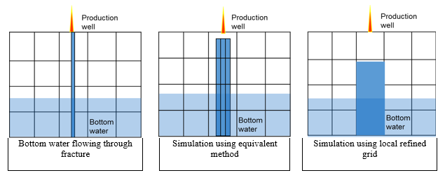
Figure 1 illustrates the simulation results using the uniform coarse and locally refined grids. It can be observed from the figure that the result from the local refinement method is more accurate; however, the coarse grid simulations can meet the engineering requirements to a certain extent.
A conceptual model with a predefined fracture size is designed based on the well spacing of a geological model, production rate, and injection rate. The fracture is simulated using uniform and non-uniform grid simulations separately. The limit is considered to be reached when results from the two simulation methods become remarkably different. Such fractures require special treatment, for which methods include refining grids locally and conducting accurate explicit simulations based on unstructured grids. Equivalent simulation using a uniform grid is conducted for small and medium fractures.
Equivalent method for small and medium-sized fractures
Equivalent permeability is a key parameter in the equivalent numerical simulation of the fractured reservoir. Numerous experts and scholars have conducted research on the calculation methods of equivalent permeability. Yongfei31 calculated the equivalent absolute permeability derived from the application of Darcy’s law by measuring the flow rate through the fracture and pressure gradient.
In this paper, the equivalent permeability of the pore grid traversed by a single fracture in the horizontal direction is calculated in order to obtain the equivalent flow rate, following which the equivalent permeability of the pore grid traversed by a single fracture in a random direction is derived.
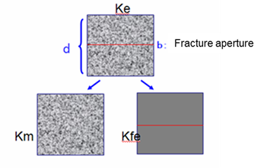
Firstly, the fracture permeability is determined according to its shape and flow characteristics. The fracture permeability can be calculated using turbulent and laminar flow, respectively, and it is equivalently distributed to fine grids in order to obtain the equivalent fracture permeability on the fine grids. For medium and small fractures, this equivalent step is easy to implement by means of modeling software. The permeability of pores is obtained by modeling of the pores. The schematic can be seen in Figure 2.
A general fracture in a vuggy reservoir has a certain aperture, and the permeability can be calculated by the pipe flow formula1:
(1)
For a horizontal fracture through the pores, as illustrated in the figure, the equivalent permeability is expressed as
(2)
For a fracture in any direction, the equivalent permeability is derived as follows:
(3)
Based on the theoretical deduction above, the equivalent permeability of a fracture through pores on a fine grid is equal to the sum of the equivalent fracture permeability of the fracture and equivalent pore permeability. Thereafter, the permeability on a coarse grid can be obtained by means of a general up-scaling method.32
Determination of fracture scale limit
In numerical simulations, appropriate simulation method should be chosen for fractures with varying scales prior to conducting fracture simulations. For Whether to use the equivalent uniform or local refinement simulation depends on the fracture scale. The following procedures are implemented in this paper to determine the fracture scale limit. Firstly, the conceptual model is designed based on well spacing, production and injection rates, and other parameters, based on a real geological model. Secondly, the dynamic data of the production wells are calculated by uniform and non-uniform grid simulation methods separately. Thirdly, the calculation differences in the main variables of the two simulation methods, such as pressure and saturation, are evaluated. When the calculation error between the two results exceeds a given error limit, it indicates that the error from the uniform grid simulation is large, so the fracture requires special simulation, and the fracture scale can be considered as the fracture scale limit.
A numerical simulation technology to fractured-vuggy carbonate reservoirs has been studied and a numerical simulation software KARSTSIM is developed, which is only used to make a study other than commercial purpose at the present.27 The software can simulate naturally fractured reservoirs and fractured-vuggy reservoirs based on a multiple-porosity method and unstructured grid. The following conceptual model is simulated by the software
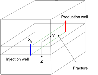
The conceptual model consists of 10 x 10 x 10 grids in three directions. The grid dimensions are 50 x 50 x 10 m. There is a fracture in the middle of the sixth layer in the longitudinal direction of the model. The production well is connected to the injection well by a fracture, and the daily injection rate of the injection well is 100 m3. The bottom hole pressure is set to the original formation pressure for the production.
Initially, the fracture aperture is 0.2 mm, the matrix permeability is 100 md, and the porosity is 0.1. When using the uniform coarse grid equivalent simulation method, the equivalent permeability in the three directions of X, Y, and Z is 100, 113, and 113 md, respectively. If the grids in the X-direction are refined to 10 m, 1 m, and 0.2 mm, the equivalent permeability in the Y and Z directions is 166 md, 767 md, and 3.33*106 md, respectively. Then, the matrix permeability is changed to 10 md. The grid is refined to 0.2 mm, and consequently, the grid permeability of the fracture is 23.3, 76.6, 676.6, and 3.33*106 md, respectively. It is worth noting that when the grid is designed as 0.2 mm, which is equal to the fracture opening, the fracture permeability is the true permeability of the fracture calculated directly from the flat plate model. Moreover, the grids differ from the surrounding matrix, and the grid porosity should be taken as 1. Figure 3 shows the conceptual model.
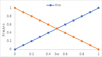
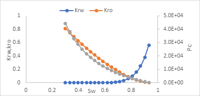
For non-uniform method, the oil and water two phase flow relative permeability in fracture grid and matrix grid are shown in Figure 4 and Figure 5 separately. For uniform method, the relative permeability and curve is shown in Figure 4. All the data is obtained by experimental measurements and capillary pressure can be ignored in fracture grid according to experimental measurements.
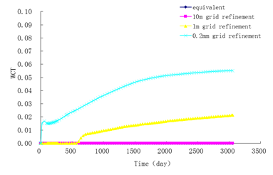
Figure 6 illustrates the saturation contours after injecting water simulated separately by the equivalent grid method on the original grid and the above three local refinement methods. According to the calculation result when using the conceptual model, the fracture scale limit is closely correlated to the permeability of the pores. When the permeability of the pores is 10 md, if the fracture opening is greater than 0.2 mm, the simulation results from the equivalent coarse grid method and locally refined grid method exhibit significant differences, as illustrated in Figure 6. When the permeability of the pores is 100 md, for a fracture with an opening greater than 0.2 mm, the simulation results from the two methods are similar, as illustrated in Figure 7. When the fracture opening is increased to 2 mm, the simulation results from the two methods exhibit an obvious difference, as illustrated in Figure 8. Figure 9 presents the water production curves of the production well when the pore permeability is 10 md and the fracture opening is 0.2 mm. Likewise, Figure 10 displays the water production curves when the pore permeability is 100 md and the fracture opening is 2 mm. The figures indicate that, for different pore permeability, the fracture scale limit, which plays a significant role in connecting the injection and production wells, is a relative value.

|
Figure 6 Injection and production well saturation fields (fracture aperture: 0.2 mm; matrix permeability: 10 md) |

|
Figure 7 Injection and production well saturation fields (fracture aperture: 0.2 mm; matrix permeability: 100 md) |

|
Figure 8 Injection and production well saturation fields (fracture aperture: 2 mm; matrix permeability: 100 md) |
|
Figure 9 Injection and production well saturation fields (fracture aperture: 2 mm; matrix permeability: 100 md) |
The above simulation results demonstrate that the fracture scale limit in numerical simulations is a relative value, depending on the permeability of the pores surrounding the fracture. When the pore permeability is low, even the simulation of a small fracture requires special treatment, such as refined grids, similar to a large fracture. However, when the permeability is high, the equivalent coarse grid simulation of a small fracture can meet the requirements, and special treatment only needs to be applied for large fracture simulations. Higher pore permeability results in a higher fracture scale limit.
Conclusions
In numerical simulations of fractured vuggy reservoirs, the fracture scale limit for large fractures depends not only on the physical characteristics of the fractures, but also on the permeability of pores. Higher pore permeability results in a larger possible fracture scale limit. For those classified as large fractures, simulations using equivalent uniform coarse grids can result in significant errors, and locally refined grids are required.
References
- Song Xiaochen, Study on discontinuum numerical models for low in fractured rock and its engineering applications. Chinese Journal of rock mechanics and engineering. 2004;23(24).
- Song Xiaochen Xu Weiya. A study on conceptual models of fluid flow in fractured rock. Rock and Soil Mechanics. 2004;25(2):226-232.
- Lv Xinrui, Han Dong, Li Hongkai. Study on the Classification and Modeling of fracture-vug oil deposits. Journal of Southwest Petroleum University(Natural Science Edition). 2018,40(1):68-77.
- Wang Jianfeng. Peng Xiaolong, Wang Gaowang et al. Method of selecting the flow model for the fracture–cavernous reservoir. Pgre. 2009;16(5):86-88.
- Snow D. Anisotropic permeability of fractured media. Water Resour Res.1969;5:1273-1289.
- Oda M Permeability tensor for discontinuous rock masses. Geotechnique. 1985;35:483-495.
- Barenblatt G I, Zheltov IP.Kochina IN. Basic concept in the theory of homogeneous liquids in fissured rocks. J Appl Math. 1960;24:1286-1303.
- Kazemi H, Porterfield K, Zeman P. Numerical simulation of water-oil flow in naturally fractured reservoirs. Old SPE.1976;16:317-326.
- Lemonnier P,Bourbiaux B. Simulation of naturally fractured reservoirs. State of the art. Part 1 physical mechanisms and simulator formulation. Oil Gas Sci Technol. 2010;65:239-262.
- Lemonnier P,Bourbiaux B. Simulation of naturally fractured reservoirs. State of the art. Part 2 matrix-fracture transfers and typical features of numerical studies physical mechanisms and simulator formulation. Oil Gas Sci Technol. 2010;65:263-286.
- Noorishad J,Mehran M. An upstream finite element method for solution of transient transport equation in fractured porous media. Water Resour Re. 1982;18:588-596.
- Kim JG, Deo MD. Finite element, discrete-fracture model for multiphase flow in porous media. AIChE J, 2000;46:1120-1130.
- Karimi-Fard M, Firoozabadi A. Numerical simulation of water injection in fractured media using the discrete-fracture model and the Galerkin method. SPE Reserv Eval Eng. 2003;6:117-126.
- Huang Zhaoqin, Yao Jun, Wang Yueying et al. Numerical Simulation on Water Flooding Development of Fractured Reservoirs in a Discrete-fracture Model. Chinese Journal of Computational Physics. 2011;28(1):41-49.
- Yao Jun, Wang Zi sheng, Zhang Yun et al. Numerical simulation method of discrete fracture network for naturally fractured reservoirs. Acta Petrolei Sinica. 2010;31(2),284-288.
- Huang Z Q, Yao J, Wang YY, et al. Numerical study on two-phase flow through fractured porous media. Sci China Technol Sc. 2011;54:2412-2420.
- Lee SH, Lough MF, Jensen CL. Hierarchical modeling of flow in natured formations with multiple length scales. Water Resour Res. 2001;37:443-455.
- Li L, Lee SH. Efficient field scale simulation of black oil in a naturally fractured reservoir through discrete fracture networks and homogenized media. SPE Reserv Eval Eng. 2008;11:750-758.
- Moinfar A. Development of an efficient embedded discrete fracture model for 3D compositional reservoir simulation in fractured reservoirs. SPE J. 2014;19.
- Moinfar A, Varavei A, Sepehrnoori K, et al. Development of a novel and computationally-efficient discrete-fracture model to study IOR processes in naturally fractured reservoirs. SPE Improved Oil Recovery Symposium.Tulsa, Oklahoma: 2012.
- M Karimi-Fard, LJ Durlofsky, and K Aziz. An efficient discrete fracture model applicable for general purpose. SPE 79699.
- KJ Slough, EA Sudicky, PA Forsyth. Numerical simulation of multiphase flow and phase partitioning in discretely fractured geologic media. Journal of Contaminant Hydrology. 1999; 40:107–136.
- R Therrien, EA Sudicky. Three-dimensional analysis of variably-saturated flow and solute transport in discretely-fractured porous media. Journal of Contaminant Hydrology. 1999;23:l-44.
- M Karimi-Fard, LJ Durlofsky, and K Aziz. An efficient discrete fracture model applicable for general purpose. SPE 79699.
- KJ Slough, EA Sudicky, PA Forsyth. Numerical simulation of multiphase flow and phase partitioning in discretely fractured geologic media. Journal of Contaminant Hydrology. 1999;40:107-136
- R Therrien, EA Sudicky. Three-dimensional analysis of variably-saturated flow and solute transport in discretely-fractured porous media. Journal of Contaminant Hydrology.1996;23:l-44
- ZJ Kang,YS Wu,JL Li. Modeling Multiphase Flow in Naturally Fractured Vuggy Petroleum Reservoirs. SPE102356,24–27 September 2006.
- YS Wu, HH Liu, GS Bodvarsson. A triple-continuum approach for modeling flow and transport processes in fractured rock. Journal of Contaminant Hydrology. 2004;73(1):145-179.
- Zhang Dongli. A research progress on mathematic model and application of fluid flow for carbonate vuggy reservoir. Journal of Southwest Petroleum Institute. 2009;31(6):66-70.
- Gao Yanxia, Li Xiaobo, Peng Xiaolong, Zhang Xiao. The Equivalent Simulation of Big Size Cavity-fracture in Cavity-fractured Reserviors. Journal of Yangtze University(Natural Science Edition. 2016;13(14):66-69.
- Yang Yongfei, Liu Zhihui, Sun Zhixue, An Senyou, Zhang Wenjie, Liu Pengfei, Yao Jun, Ma Jingsheng. Research on stress sensitivity of fractured carbonate reservoirs based on CT technology. Energies. 2017;10(11):1833.
- Durlofsky LJ. Representation of grid block permeability in coarse scale models of randomly heterogeneous porous media. Water Resources Research. 1992;28(7):1791-1800.
